
Load Cell Configuration
In the diagram below, the two axial strain gauges, shown as resistances R1 and R3, change in resistance by some similar amount.
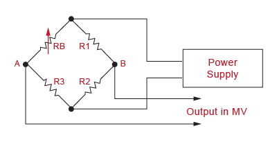
The two transverse gauges, shown as RB and R2, also change in resistance, but opposite in sense to the change of RI and R3.